555 Timer Wiring Diagrams
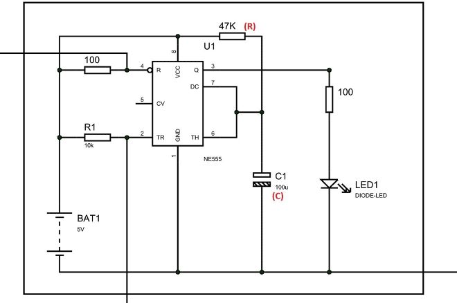
In astable mode, the 555 timer acts as an oscillator that generates a square wave. Other circuit uses diodes to split the charging and the discharging paths through different resistors, but here we need no such diodes.
 Pin on Electronic Circuits
Discover the basics of the 555 timer and how to set it up to operate in monostable mode, along with a sample circuit you can build yourself..

555 timer wiring diagrams. They are used for the safety of people to detect anyone carrying a metal (Arms etc). This 555 timer circuit will remain in either state indefinitely and is therefore bistable. The 555 timer is a chip that can be used to create pulses of various durations, to output a continuous pulse waveform of adjustable pulse width and frequency, and to toggle between high and low states in response to inputs.
This 555 timer clap switch… Collect all useful circuits for you. It includes all of the wiring diagrams and instructions you need to get started.
It includes all of the wiring diagrams and instructions you need to get started. The 555 timer IC is an integrated circuit (chip) used in a variety of timer, pulse generation, and oscillator applications. Explanation of Terminals for 8 pin 555 Circuit and Wiring Diagram Download for Automotive, Car, Motorcycle, Truck, Audio, Radio, Electronic Devices, Home and House Appliances published on 12 Nop, 2018.
Let us discuss in detail about this circuit. Posted by Circuit Basics | DIY Electronics. Then the Bistable 555 timer is stable in both states, “HIGH” and “LOW”.
These on off intervals can be adjusted by varying the 555 timer output and number of counter outputs. An Overview of the 555 Timer The 555 Integrated Circuit (IC) is an easy to use timer that has many applications. Kartik, the Tn equation is correct.
555 Timer Basics – Monostable Mode. The 555 Timer IC Circuit and Wiring Diagram Download for Automotive, Car, Motorcycle, Truck, Audio, Radio, Electronic Devices, Home and House Appliances published on 12 Nop,. In this project we are going to design a simple metal detector circuit.
The schematic shown below is a 555 timer circuit. The threshold input (pin 6) is connected to ground to ensure that it cannot reset the bistable circuit as it would in a normal timing application. By wiring the 555 timer with resistors and capacitors in various ways, you can get it to operate in three different modes:
This circuit has many applications on places where it is necessary to activate and deactivate (connect and disconnect) an electrical or electronic device. 555 timers are very popular in. LM555 Timer 1 Features 3 Description The LM555 is a highly stable device for generating 1• Direct Replacement for SE555/NE555 accurate time delays or oscillation.
There is a huge list of 555 IC circuits due to which this IC is very popular among electronics hobbiests, students and experimenters. Configurations like that of an egg timer, automatic day/night lamp. A square wave oscillator using 555 IC can be configured to give symmetric oscillation (50% duty cycle).
With this information you will learn how how the 555 works and will have the experience to build some of the circuits below. The 555 timer is a simple integrated circuit that can be used to make many different electronic circuits. In this project, we are using 555 Timer IC to create various timer circuit like 1 min timer circuit, 5 min timer circuit, 10 min timer circuit, and 15 min timer circuit.
Here, with the help of the 555 timer IC, we are eliminating the need of manually switching ON or OFF the device. From the above discussion, it is concluded that for the having low output from the timer 555, the voltage on the threshold input must exceed the control voltage or + (2/3) V CC. Additional • Timing from Microseconds through Hours terminals are provided for triggering or resetting if • Operates in Both Astable and Monostable Modes desired.
Wiring diagram with IC 555 use.. The IC 555 as we all know is a universally acclaimed work-horse IC which finds almost unlimited number of applications through various different electronic circuits. The circuit mentioned here is a ten minutes timer, after pusing
Ic circuit diagram ic power amplifier circuit diagram ic circuit diagram pdf - 555 ic circuit diagram ic circuit diagrams ic circuit diagrams 40w ic amp circuit diagram ic input mixer circuit diagram circuit diagrams for ic 7485 ic input mixer circuit diagram . As the name indicates, only one state is stable and the other one is called unstable or quasi stable state. According to the datasheet for the 555 Timer, astable output, the following formulas are used (this is how the calculator works).
This also turns the discharge transistor on. Simple time delay circuit diagram using 555 timer electtonics dc power delay circuit electronic circuits and diagramelectronics Bistable Multivibrator mode of 555 timer IC is the easiest mode of 555 timer IC, where Monostable multibrator mode has one stable and one unstable state. It is widely used in electronic circuits and this popularity means it is also very cheap to purchase, typically costing around 30p.
555 timer IC remains in Stable state until the external triggering is applied. Monostable multivibrator (MMV) mode of 555 timer IC is also called Single shot mode. 555 TIMER Timers, as the name specified, are the electronics circuits used for measuring time intervals.In this article, we will cover about 555 timers.
This integrated circuit can be used in a variety of ways from which the basic one is to produce accurate and stable delays in electronic circuits.Additionally, it is available in 8 pin DIP and 14 pin DIP. This ON-OFF Switch circuit using a 555 timer is simple, useful and easy to implement. The 555 timer IC is an integral part of electronics projects.
ON-OFF Switch circuit using a 555 timer. Adjustable ON OFF Timer(using 555 astable mode) In this circuit a timer with cyclic on off operations is designed. The frequency of the wave can be adjusted by changing the values of two resistors and a capacitor connected to the chip.
The picture with the title Ic Circuit Diagram 555 Timer Wiring Library above, tagged with:
 555 adjustable timer circuits Google Search Tech Wise
 555 Timer in Astable Mode to Control 3*3*3 LED Cube
 Ding dong door bell using 555 timer circuit diagram
 74LS32 Pinout Pin Diagrams Circuit diagram, Electronic
 Voltage Doubler Circuit Diagram in 2019
 Police Siren Circuit using NE555 Timer Police siren
 Pinterest
Automatic Rain Sensing Wiper using 555 Circuit Diagram
 Switchable Monostable 555 Timer Circuit at Four Rotary
 12V / 230V 50Hz square wave inverter with 555 DIY DC/AC
 Monostable operation delay on NE555 circuit used to
 Pin by Febin Antony on My Funny Electronics in 2019
 Sinking and Sourcing the 555 Timer in 2019 Diy
 555 Timer Circuits/Projects for Engineering Students
 RGB LED Bulb using 555 Timer ICs Circuit diagram
 NE555 Police Siren Circuit Police siren, Electronics
 Here is a simple electronic projects of relay toggle
 LED flasher circuit Electronics in 2019 Electrical
 Switchable Monostable 555 Timer Circuit at Four Rotary
 Pin on 555 Timer Circuits
 Pinterest
 Pin on 555 Timer Circuits
 555 Timer Calculator Electronics Electronics, Circuit
 Astable Multivibrator Circuit Using 555 Timer Output
 1 Minute Timer Circuit Diagram Electronic Circuits
 555 timer kit by getlowfi Google Search Diagram, Kit, Wire
 555 Timer Time Delay Circuit electronics Circuit
 automatic street light using 555 timer circuit in 2019
 555 Timer Bistable Multivibrator Circuit Diagram Circuit
 Police Siren Circuit using NE555 Timer
 555 Timer Circuit Diagram With Variable On/Off Times
 TALKING ELECTRONICS 555 Page3 alarm Pinterest
 PWM based LED Dimmer Using 555 Circuit, Block Diagram
 Sine wave generator circuit with 555 timer Electric
 Square wave Pulse Generator using 555 timer in 2019
 Pin on Electronic Circuits
 Pin on 555 Timer Circuits
 Servo Tester using 555 timer Circuit Diagram Electronics
 The 555 Monostable Circuit More Detail Electronics
 555 variable pulse generator Electronics Pinterest
 Circuit Diagram for Strobe Light using 555 Timer IC 555
 Voltage Doubler Circuit using 555 Timer with Working
 Heart Shaped Serial LED Flasher Circuit Diagram 555
 555 Pin Layout Electronics Knowledge Pinterest
 555 timer delay circuits Electronics Electronic
 Pin on Electronic Circuit Diagrams
 4 way Traffic Lights Diagram. Tech Gadgets Pinterest
 Circuit Diagram for Quiz Buzzer using 555 Timer IC
 Pin on Electronic Circuit Diagrams
 555 Timer Block Diagram in 2019 Block diagram, Diagram
 555 Timer Circuit Diagram Police Siren Simple Schematic
 Pin on Electronic Designs
 Pin on diy synth and audio
 Switchable Monostable 555 Timer Electronics projects
 555 Timer Pin Out Diagram in 2019 Diy electronics
 Pin by Jek on electronics for kids Hobby electronics
 Pin on Electronic Circuits
 Pin on circuit diagram electronics
 555TimerLightSensitiveScreamerSirenCircuitKit
 Pinterest • The world’s catalog of ideas
 Fire Alarm Project using Thermistor and IC 555 555 Timer
 Pin on 555 circuits
 Adjustable Timer Circuit Diagram with Relay Output
 Pin by Gene Hudson on Electronic Schematics Electronic
 Make an LED Blaster Electronics components, Electronics
 LED Chaser Circuit Diagram Electronic schematics
 555 Timer 7 Segment Display Counter Circuit Diagram in
 Basic timer control with 555TimerIC Circuit is an
 555 Twotone experiment Electronics projects, Electrical
 Common Mistakes When Using a 555 Timer in 2019
 simple adjustable IC 555 timer circuit with relay
 555timer based water level controller Electronic
 555 Timer as an Astable and Monostable Multivibrator
 In this post we learn how to make a simple IC 555 based
 LED Pattern Flasher Using 555 Timer, 4017 Counter and
 Servo tester by 555 timer » Current Projects Electronics
 Pin on 555 Timer Circuits
 micro inverter schematic diagram Google Search
 Metal detector, Electronic circuit and Metals on Pinterest
 Pin on STEAM education projects
 Fig. 5, 555 timer Tester 555 Pinterest Gadget
 Running LED effects using 555 timer IC. LED Circuits
 555 adjustable timer circuits Google Search Circuit
 555 Timer Astable Circuit Calculator 555 Timer Circuits
 555 Timer Astable Multivibrator Circuit 555 Timer
 Touch ON and OFF Switch Circuit Diagram and Working DIY
 Pin on Electronics
 555 Timer Output Driver Electronics basics, Diy
 12V Power Inverter using 555 Timer Circuit Diagram mu in
 50 555 Circuits Electronics components, Diy
 Pin on Electronic Circuits
 Component, Monstable Multivibrator Using 555 Timer
 Pin on Pinned electronic circuits
 Monostable 555 Timer Electronics projects for beginners
 555 Electronic Metronome Circuit Electronics, Electrical
 555 Timer Based Simple Electronic Code Lock Circuit
 Pin on Books Worth Reading
 Clap On Clap Off Switch using 555 Timer IC Electronic
 Police Lights Circuit using 555 Timer and 4017 Decade


Comments
Post a Comment